
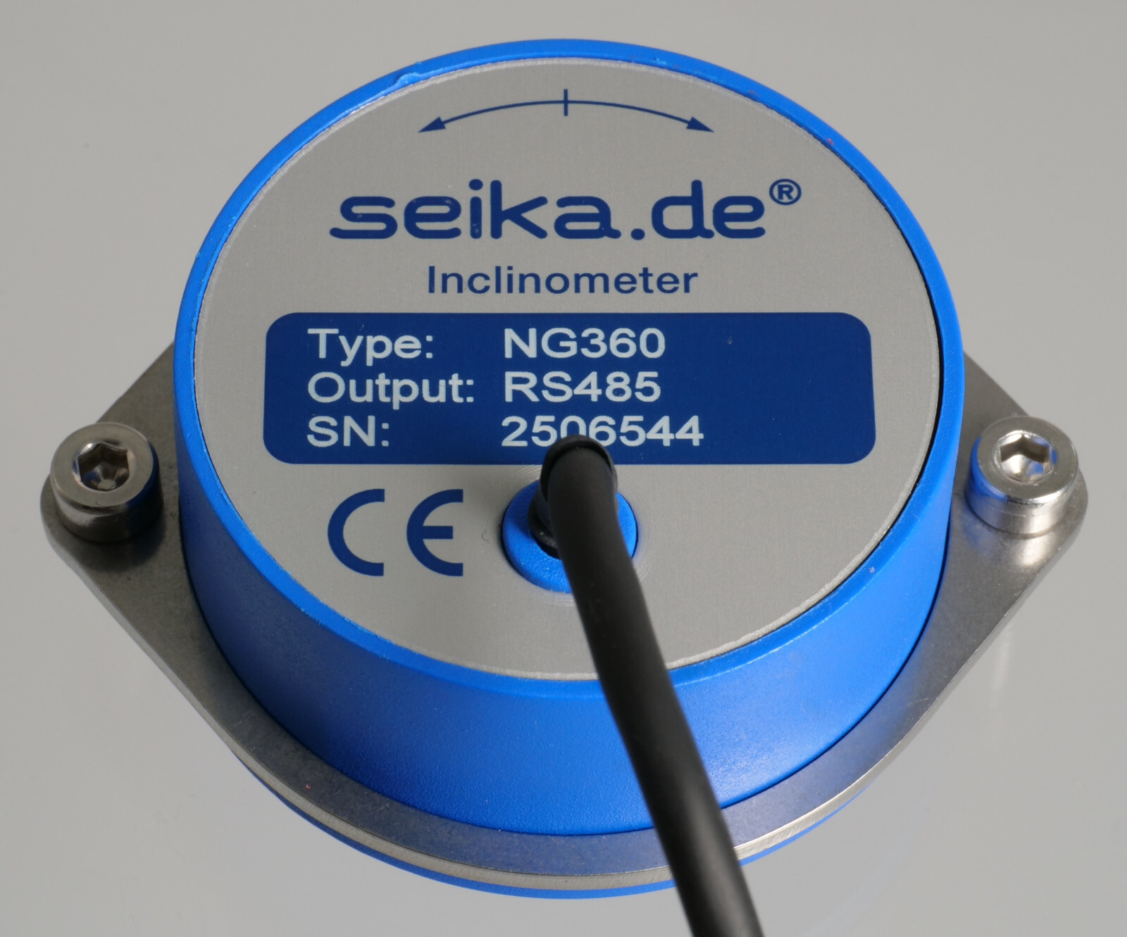
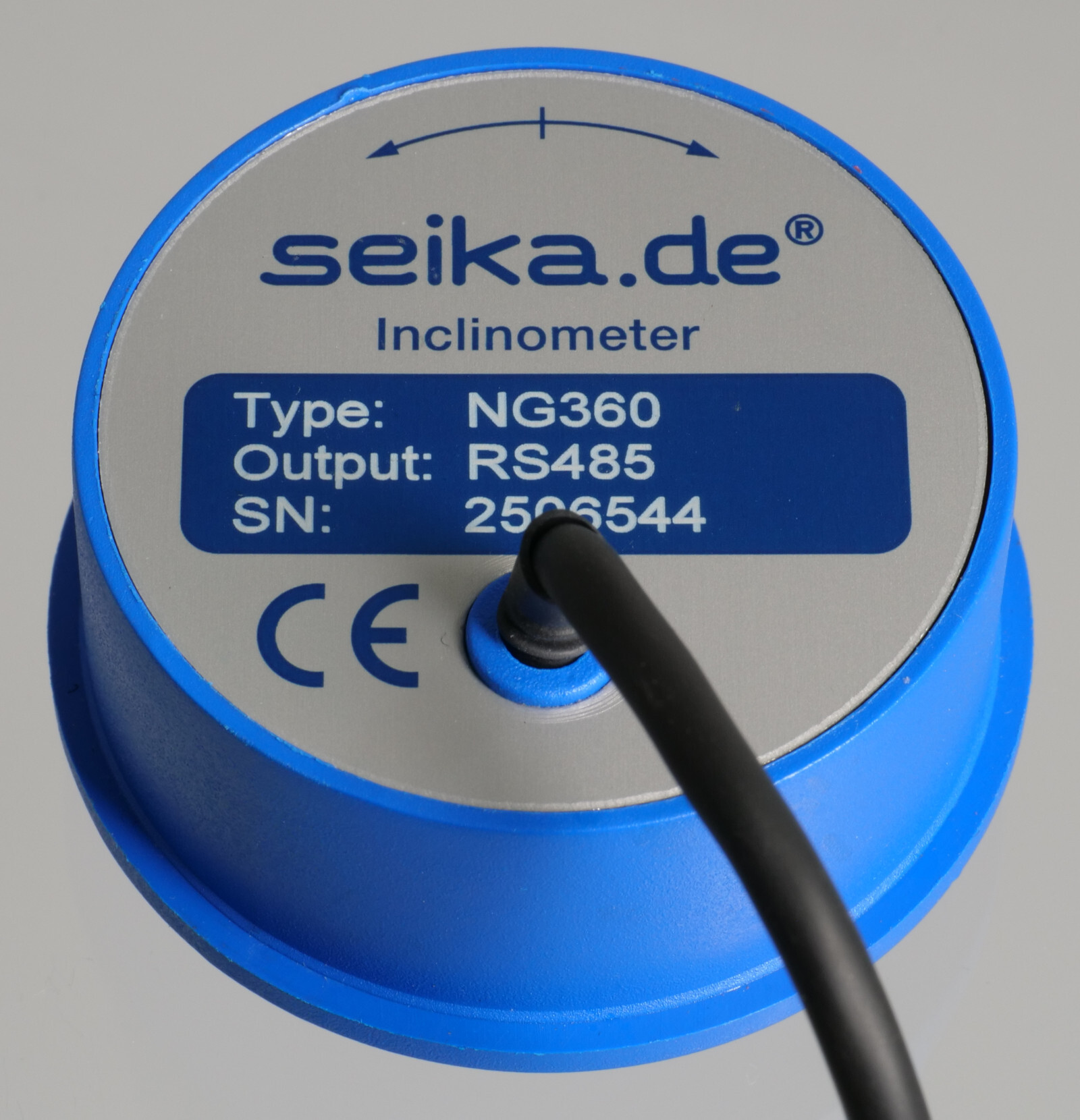
Inclinometer with digital RS485 communications port and 360 degree measuring range
Features
- integrated 16bit microprocessor
- RS485 bus output signal
- no measuring range limitation
- 0.01 degree resolution
- minimal linearity deviation
- high long-term stability
- hysteresis free output signal
- minimal zero point drift
- no interference by ambient electromagnetic fields
- shockproof as without moving mechanical parts
- hermetically sealed
- sensor electrically isolated from point of measurement - no ground connection
- zero point adjustable through 360° using clamping ring
- integrated temperature measurements correct for temperature related measurement inaccuracies
Description
The NG360 is a capacitive, liquid based inclinometer with integrated sensor electronics and 16 bit microprocessor. The measurement result is transmitted via a RS485 port for further processing. Up to 78 sensors can be operated using a single communications line. The measurement method provides a linear relationship between the angle to be measured and the output signal. The determined angle is independent of the local gravitational acceleration, that means that no matter where the measurement is being taken, whether in Europe, Australia, on Mount Everest or on the moon, the inclination will be measured correctly anywhere. Temperature related inaccuracies are corrected by the integrated microprocessor.
Application
The NG360 inclinometer is suitable for applications requiring the measurement of any angle for further processing on a PC. Typical areas of application include construction, mining, vehicles, aircraft, ships, surveying equipment, and transportation and conveyor systems.
Specifications
| Type | NG360 |
|---|---|
| Measuring range | 360 degrees |
| Resolution | 0.01 degrees |
| Dimensions | see dimension drawing |
| Linearity deviation | ±0.25 degrees |
| Transverse sensitivity | < ±0.1 degree at 45° tilt |
| Settling time | approx. 0.3 seconds |
| Supply voltage UbN | 9V ... 15V |
| Supply voltage on-transition time | < 50ms |
| Current drawn | approx. 30mA |
| Degree of protection | IP65 |
| Operating temperature | -40°C ... +85°C |
| Storage temperature | -45°C ... +90°C |
| Weight (without clamping ring or cable) | approx. 141g |
| Electrical connection | 2m shielded cable Ø4.6 mm |
- • Each sensor is calibrated after production. It is delivered with an individual calibration record that includes the precise offset and sensitivity values, the static characteristic curve and the linearity deviation curve.
- • On request: custom wiring
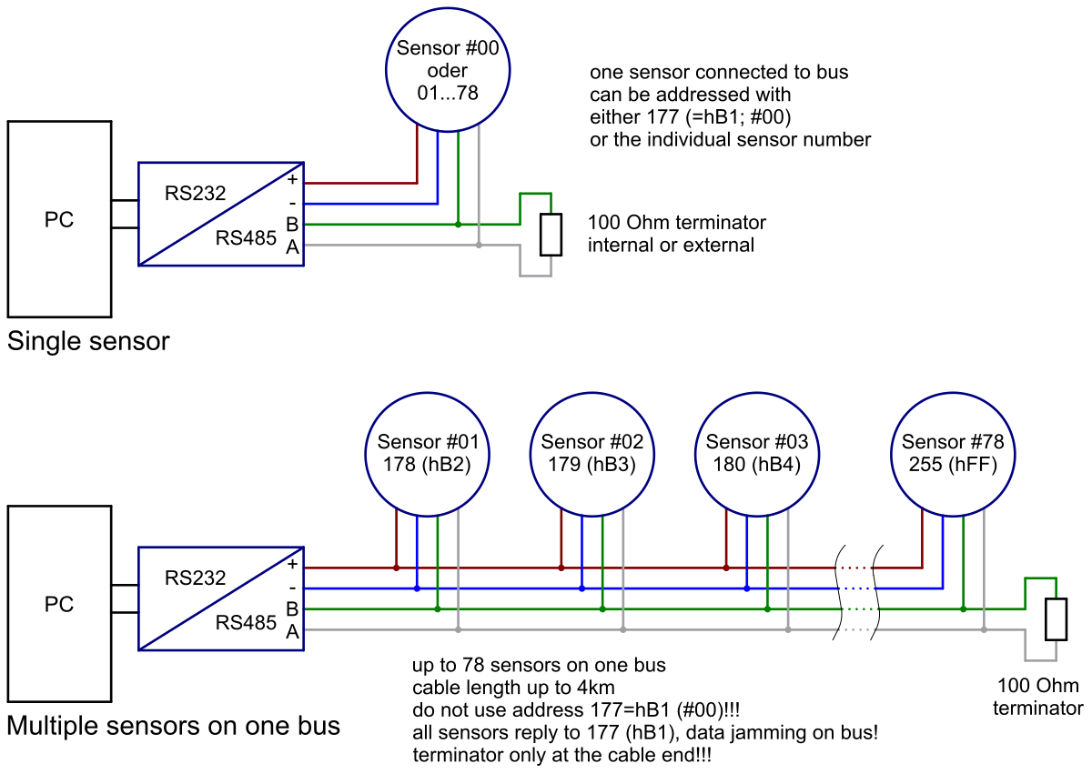
NG360 sensor connection to RS485 bus
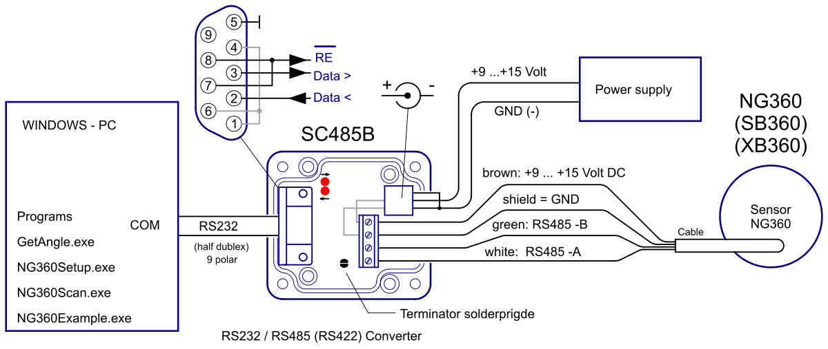
Connection to SEIKA RS232/RS485 converter SC485B
Dimensions (in mm)

Data transmission protocol of measured angle
Angles can be received from a connected PC as follows:
- Send: Address (1 byte, B1 to FF)
- Send: ENQ (1 byte, 05)
- about 10ms pause (switching from receive to transmit in sensor)
- Receive: STX (1 byte, 02) + angle (6 bytes ASCII, e.g. '359.99') + ETB (1 byte, 17)
- Receive: checksum (2 bytes ASCII, e.g. '04') + $ (24)
- about 10ms pause (switching from transmit to receive in sensor)
- Send: if checksum is correct: ACK (06), otherwise: NAK (15)
- if ACK: terminate, if NAK: go to 3
Computing the checksum
The checksum is computed as the XOR combination of the bytes immediately preceding it in the sensor output and is transmitted as an ASCII encoded 2-byte hexadecimal value. For example, a valid sensor output is:
Sensor: 02 '3' '5' '9' '.' '9' '9' 17 '0' '4' 24
In this case, the value of the checksum 04 is computed as:
02 XOR '3' XOR '5' XOR '9' XOR '.' XOR '9' XOR '9' XOR 17
= 02 XOR 33 XOR 35 XOR 39 XOR 2e XOR 39 XOR 39 XOR 17
= 04
Cable specification PC to SC485B
The SC485B RS232/RS485 converter can be connected directly to the RS232 output of the PC or USB to RS232 converter. Alternatively, a 1:1 or straight-through RS232 cable can be used to interface with the PC.
PC COM port settings for the RS232/RS485 converter
| bits/second | 9600 |
| data bits | 8 |
| parity | no |
| stop bit | 1 |
| handshaking | no |
Software (Windows 95 - Windows 11)
To display the measurement results and configure the sensor the following programs can be used. They run on any Intel-compatible PC
on Windows 95/98 up to Windows 11. It is recommended to save the software locally before execution.
The software is tested and fully functional when used with the SEIKA RS232/RS485 interface converter SC485B. Attempting the use
of other converters is possible, but in this case we cannot guarantee full functionality.
Although the NG360 will operate from any half-duplex RS485 port, we recommend using the SEIKA interface converter SC485B for
an easier initial setup.
GetAngle GetAngle.exe GetAngle.zip
This program displays the angle of one or more NG360, which are connected through a RS232/RS485-Converter (i.e. SEIKA SC485B) to the PC. The serial port COM.., the sensor address and the display speed (averaging of several measurements) can be adjusted. Additionaly, measurements can be saved to a logfile in regular time-intervals, for further processing i.e. with MS Excel.
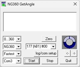
If more than one sensor is connected to the same bus, the address 177 (hB1) #00 (as in the figure above) must not be used.
Since they always respond to the base address 177 (hB1), all the sensors would then answer simultaneously, inevitably causing jamming
on the data bus and preventing the transfer of useful information.
Nevertheless, the address 177 (hB1) may be used if only one sensor is active.
NG360Setup NG360Setup.exe NG360Setup.zip
This program can be used to change several parameters of the NG360. These parameters can be read, modified and then saved permanently
in the NG360 EEPROM. This does not affect any calibration values.
Attention! If more then one NG360 are configured to use the same address, this inevitably leads to a bus conflict and may damage the
bus-driver IC. Reprogramming of the addresses will then only be possible, if all but one sensor on the bus is switched off or disconnected from the bus. Every
sensor responds to the address 177 (hB1), and therefore no NG360 sensor should ever be programmed to use this address. Addressing a NG360
individually on a bus with multiple active NG360s is impossible after writing address 177 (hB1) to it. As all sensors always respond
to the base address 177 (hB1), the transmitted data would be stored in all sensors, overwriting any previous settings, in particular the
individual addresses. The latter would then have to be reprogrammed.
The serial port and respective sensor address should first be set under "PC connection settings". As above: The
address 177 (hB1) (as illustrated in the image) must not be used here if more than one sensor is connected to the bus.
Even when reading all sensors would answer to address 177 (hB1) and cause a bus conflict.
If only one sensor is active, then the address 177 (hB1) can be used, necessary if the sensor's individual address isn't known or
hasn't been assigned yet.
After that, invoking "read variables" returns the respective sensor's current configuration and displays the values in the corresponding boxes.
After setting the values for the sensor variables V024, V025, V026 and V063 in their input fields, "write variables" permanently writes them to the addressed sensor's EEPROM.
The variable V064 (delay for serial port) determines the time period between receiving and sending data from the sensor. Increasing this setting can help to ensure reliable data transfer for slow PC serial ports.
For applications requiring fast measurements, the signal filtering may be turned off by setting V025 (order of the filter)
to 0 (no filter). However, these measurements tend to be more unstable. Slow measurements using a 2nd order filter with a
low cut-off frequency (V026) display more stable measurement results.
Only one program (GetAngle.exe or NG360Setup.exe) may access the serial port at any one time, although more than one may
be running simultaneously. Any program using the above communication protocol will work with the NG360 sensors.
NG360Scan NG360Scan.exe NG360Scan.zip
You can use this program to identify every NG360 sensor connected to the bus. The program scans the whole range of possible NG360 addresses and displays the angle values send by each connected sensor.
Invoking "Scan" makes the program request a reading from each of the possible 78 addresses and wait for a response. Should a sensor respond,
then the received angle measurement is displayed above the address. After completing the scan, all active sensors can be determined by
inspection.
With "Start reading" the program will afterwards continually request and display the current angle for every active sensor connected to
the bus until terminated by clicking "Stop reading".
NG360Example NG360Example.zip
This directory contains an example program for programmers, with complete MS Visual C++ sourcecode. This open source example program developed using MS Visual C++ 5.0 provides some information how to develop interface software for the RS232/RS485 converter and the NG360 sensors.
Hardware-RESET
Upon activation of the supply voltage, the NG360 inclinometer is forced into a predefined operating state by a RESET. This procedure is important for a correct functionality of the internal microprocessor. The supply voltage rise time must be as short as possible for the RESET to be successful.
A slow supply voltage rise time or switching the sensor on, off and on again in quick succession (bouncing) can cause the programs running on the internal microprocessor to crash, giving the impression of a defective sensor. Switching the supply voltage on correctly ill start the sensor up again correctly. Similar problems can occur if the supply voltage falls below 9V or fluctuates around 9V.
The operational time for a correct supply voltage is unlimited.