
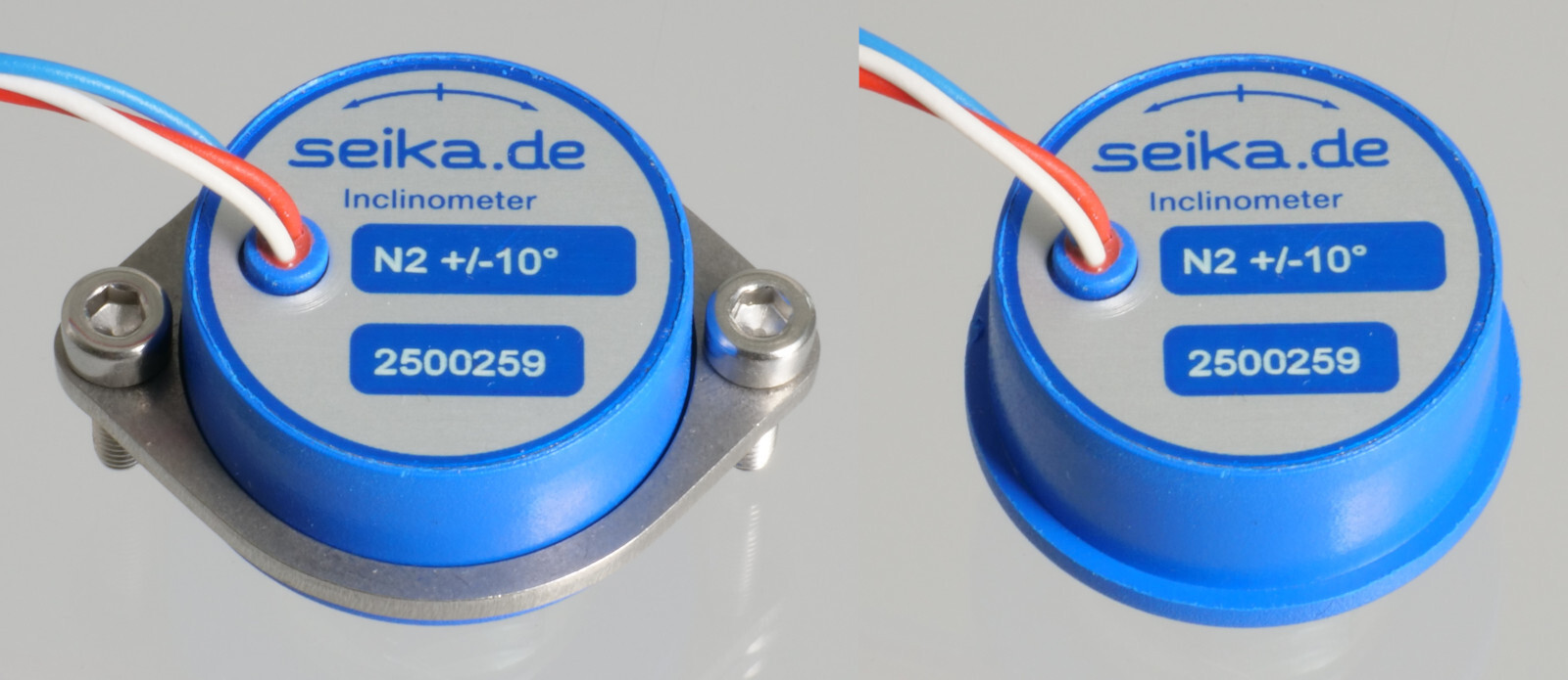
N2, N3, N4
Small inclinometers for measurements in the ranges of ±10, ±30 and ±70 degrees
Features
- linear output characteristics
- high measurement accuracy
- high long-term stability
- hysteresis free output signal
- minimal zero point drift
- integrated sensor electronics
- low power consumption
- small housing
- light weight
- different output signal options
- no interference by ambient electromagnetic fields
- shockproof as without moving mechanical parts
- hermetically sealed
- sensor electrically isolated from point of measurement using high quality plastic housing - no ground connections
- zero point adjustable through 360° using clamping ring
Description
The N2, N3 and N4 are capacitive, liquid based inclinometers with integrated sensor electronics. They are manufactured with an analog DC output. The sensor electronics require only minimal power and are in conjunction with the capacitive primary transformer characterized by high accuracy, a high signal-to-noise ratio and high long-term stability. The measurement technique enables a linear relationship between the angle to be measured and the output signal. The determined angle is independent of the local gravitational acceleration, that means that no matter where the measurement is being taken, whether in Europe, Australia, on Mount Everest or on the moon, the inclination will be measured correctly anywhere.
Application
The inclinometers N2, N3 and N4 are suitable for applications requiring a small, light sensor for measurement of relatively large inclinations. Typical areas of application include measuring instruments and inspection systems, vehicles, automation and safety engineering, scientific devices, medical and communications equipment as well as navigational systems.
Specifications
| Type | N2 | N3 | N4 |
|---|---|---|---|
| Measuring range | ±10° | ±30° | ±70° |
| Resolution | <0,002° | <0,005° | <0,01° |
| Values for analog DC output at Ub = 5 Volt | |||
| Sensitivity | approx. 12mV/degree | approx. 6mV/degree | approx. 3.6mV/degree |
| Temperature drift of sensitivity | approx. -0.19%/K | approx. -0.17%/K | approx. -0.17%/K |
| Temperature drift of zero point | approx. ±0.05mV/K | approx. ±0.025mV/K | approx. ±0.025mV/K |
| Type | N2 |
|---|---|
| Measuring range | ±10° |
| Resolution | <0,002° |
| Values for analog DC output at Ub = 5 Volt | |
| Sensitivity | approx. 12mV/degree |
| Temperature drift of sensitivity | approx. -0.19%/K |
| Temperature drift of zero point | approx. ±0.05mV/K |
| Type | N3 |
|---|---|
| Measuring range | ±30° |
| Resolution | <0,005° |
| Values for analog DC output at Ub = 5 Volt | |
| Sensitivity | approx. 6mV/degree |
| Temperature drift of sensitivity | approx. -0.17%/K |
| Temperature drift of zero point | approx. ±0.025mV/K |
| Type | N4 |
|---|---|
| Measuring range | ±70° |
| Resolution | <0,01° |
| Values for analog DC output at Ub = 5 Volt | |
| Sensitivity | approx. 3.6mV/degree |
| Temperature drift of sensitivity | approx. -0.17%/K |
| Temperature drift of zero point | approx. ±0.025mV/K |
| Shared specifications | |
|---|---|
| Dimensions | see dimension drawing |
| Linearity deviation | 0,2% of measuring range |
| Transverse sensitivity | <1% at 30° tilt |
| Settling time | <0,3 seconds |
| Nominal supply voltage (regulated externally) | UbN = 5 Volt |
| Permissible supply voltage range Ubz | 3V ... 6V |
| Mechanical overload resistance | 10 000 g (approx. 100 000 m/s2) |
| Degree of protection | IP 65 |
| Operating temperature | -40°C ... +85°C |
| Storage temperature | -45°C ... +90°C |
| Weight (without clamping ring, with approx. 18cm wires) | approx. 24g |
| Electrical connection | standard: • 3 highly flexible, color-coded wires ø ~1mm, length approx. 18 cm optional: • 0.5m strong, flexible, shielded cable, 2 wires + shield, ø2,1mm • special lengths on request |
| Values for analog DC output at Ub = 5 Volt | |
| Current drawn | approx. 1mA |
| Zero offset | 2.5±0,1 Volt - generally: 0.5Ub±4% |
| Output impedance | 10 kOhm |
- • Each sensor is calibrated after production. It is delivered with an individual calibration record that includes the precise offset and sensitivity values, the static characteristic curve and the linearity deviation curve.
- • On request: PWM-output
 3D geometry as STEP file (without clamping ring)
Dimensions (in mm) and Connections
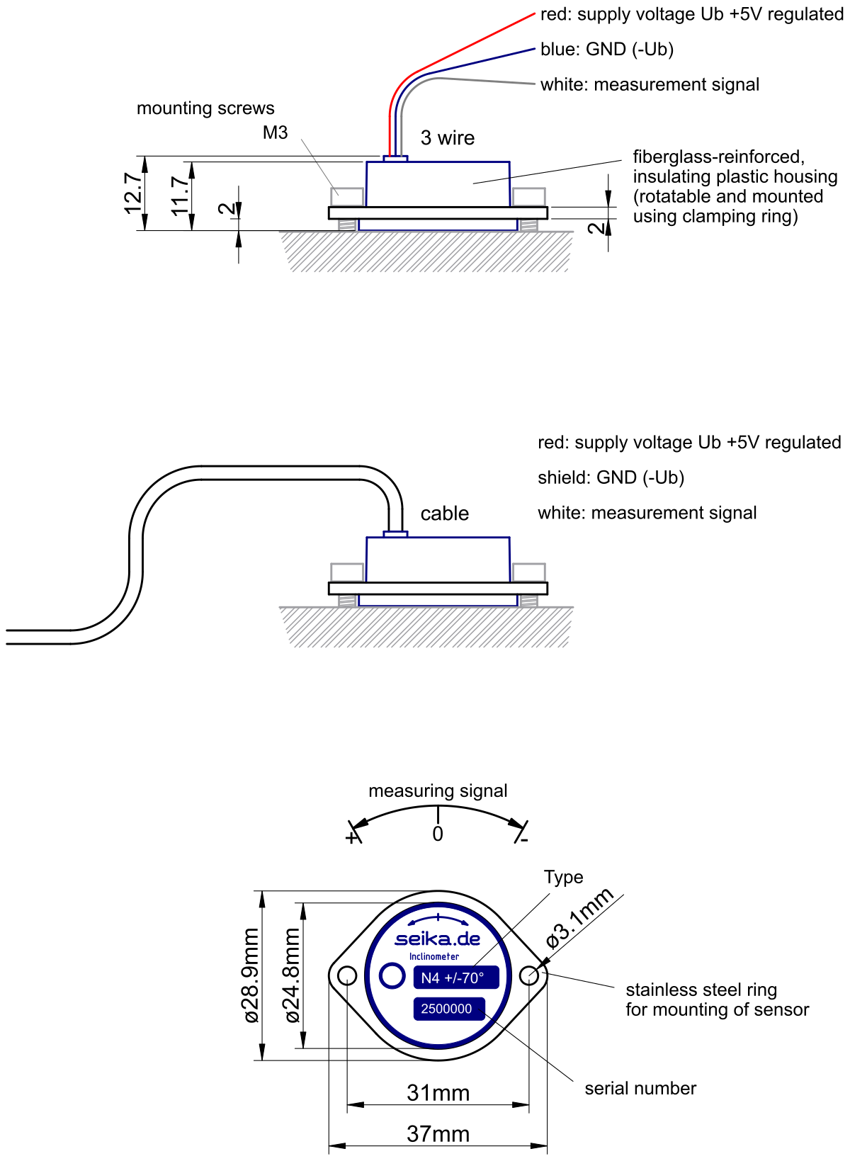
Cable assignment: red: 5V, white: output, shield: GND.