
Sensorbox containing two sensors and two signal conditioners with 4...20mA, 2-wire outputs that is ATEX certified for compliance with the 2014/34/EU directive for equipment in potentially explosive atmospheres.
Features
- ATEX certifications for the use in potentially explosive atmospheres:
II 2 G EX ia IIC T4 Gb (zone 1)
II 2 D EX ia IIIC T135°C Db (zone 21)
or
II 3 G EX ec IIC T4 Gc (zone 2)
II 3 D Ex tc IIIC T135°C Dc (zone 22) - tested according to:
EN IEC 60079-0:2018 for the use in potentially explosive atmospheres,
EN IEC 60079-7:2015/A1:2018 for equipment protection by increased safety "e",
EN 60079-11:2012 for equipment protection by intrinsic safety "i", and
EN 60079-31:2014 for equipment dust ignition protection by enclosure "t" - robust pressure die cast aluminium housing (IP67) with saltwater proof coating
- twist free 4-point fastening of rigid, 3.2mm thick base PCB
- two integrated signal conditioners with 4...20mA, 2-wire outputs
- temperature drift compensation of the sensitivity (optional: of offset and sensitivity)
- no separate supply voltage necessary
- all SEIKA sensors of the B-, BDK-, N- and NB-series can be installed in different directions of operation
- the output signals for each sensor are calibrated to customer's specifications in the required directions of operation
- sensors and signal conditioners electrically isolated from housing
- both output channels are electrically isolated from and independent of each other
- EMC certified with sophisticated protective circuitry
- internal, highly stable sensor supply voltages
- 10V ... 30V terminal voltage
- programmable dynamic response
- loop current limitation
- high mechanical overload resistance
- either connection polarity - possibility of 3-wire connection for both measuring loops
- low pass filter with optional choice of cut-off frequency for suppression of interference frequencies
- also available with a single channel
Description
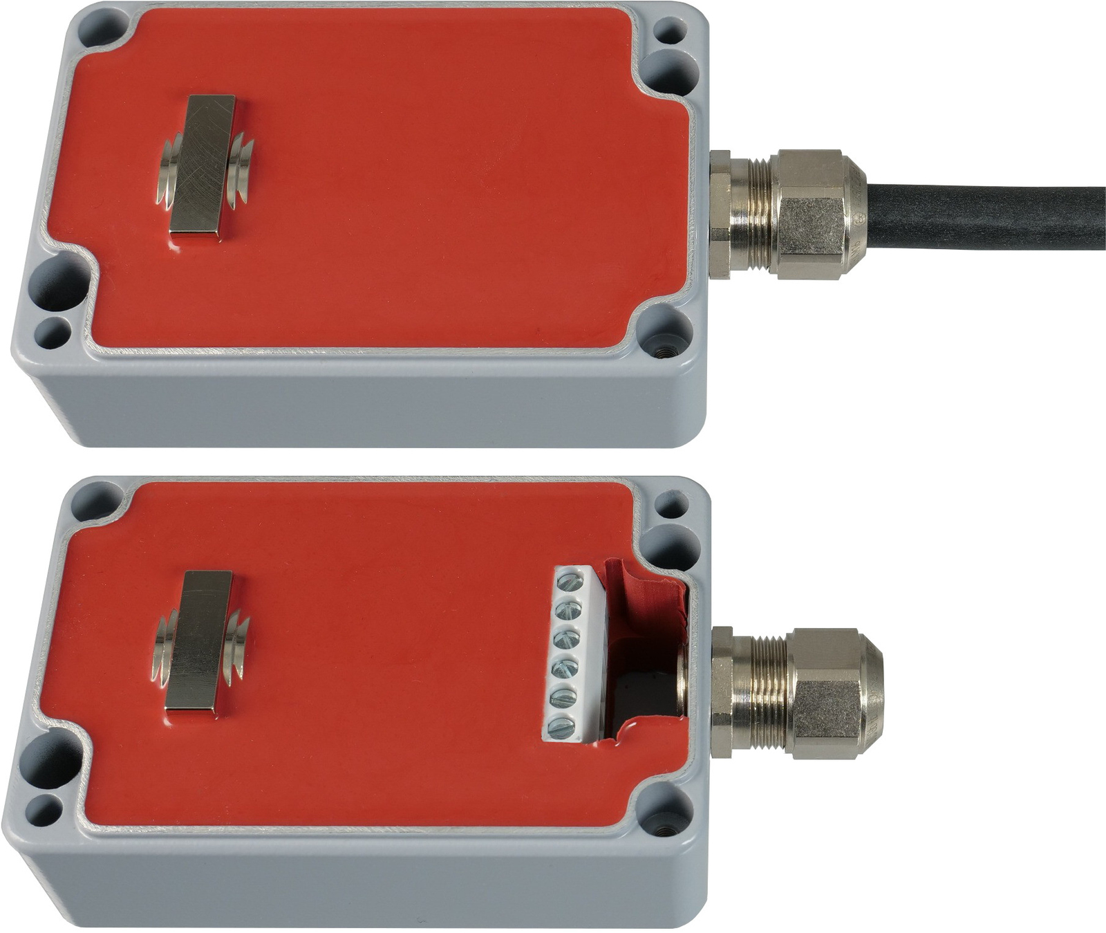
The SB2I-ATEX is a pressure die cast aluminium sensor housing (IP67) with two integrated sensors for measuring inclinations and/or accelerations along two axis for the use in potentially explosive atmospheres.
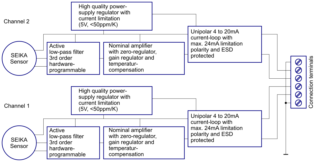
As well as the sensors, the box contains two independent signal conditioners, each with a 4...20mA, 2-wire output, and two separate, highly stable voltage supply feeding off the corresponding current loop, one for each sensor. Furthermore, each signal conditioner includes an active low pass filter, whose upper cut-off frequency / settling time can be adjusted to suit the measurement task, an output stage with current limitation, a noise voltage filter and a diode bridge for unipolar connection to the current loop. Interference signals caused by unwanted ground currents are eliminated by electrically isolating each sensor and signal conditioner from each other and the housing. Electronic temperature compensation largely compensates for the temperature drift of the implemented sensors' sensitivity. Optionally, the temperature drift of both offset and sensitivity can be reduced significantly through individual compensation.
The compact metal cable gland and small housing size in combination with the 3-wire connection enable the use of this high quality measuring system in harsh operating conditions.
Application
The SB2I-ATEX is suitable for applications requiring precise inclination or acceleration measurements along two axis in potentially explosive atmospheres and returning of a 4...20mA output signal each. It is used for, e.g., offshore, mining, in petrochemical and agricultural applications.
Specifications
| ATEX certificate number EPS 18 ATEX 1 016 X for II 2 G EX ia IIC T4 Gb (Zone 1) and II 2 D EX ia IIIC T135°C Db (Zone 21) | Maximum values per channel: Ui = 30V, Ii = 78mA Ci = 24nF, Li = 66μH |
| ATEX certificate number EPS 18 ATEX 1 017 X for II 3 G EX ec IIC T4 Gc (Zone 2) and II 3 D Ex tc IIIC T135°C Dc (Zone 22) | Nominal values per channel: Un = 30V, In = 40mA |
| Terminals | 6 x 1.5 mm2 |
| Cable gland | M16 x 1.5, metal cable gland, clamping range 8mm ... 10mm |
| Measuring range, Resolution, etc. | depending on implemented SEIKA sensors |
| Degree of protection | IP67 |
| Mounting orientation | any (standard: wall mounting, cable on the right) |
| Measuring planes (N sensors) | 3 main housing planes |
| Measuring directions (B and BDK sensors) | in X,Y,Z coordinate of housing |
| Torque housing lid | 1.5Nm |
| Terminal voltage | 10V ... 30V |
| Minimum loop currents | 2.1mA ... 3.5mA |
| Maximum loop currents | 22mA ... 26mA |
| Output signal loop current | 4...20mA (12mA for sensor zero position) |
| Adjustable variables | zero point (12mA), amplification |
| Maximum load resistances | 500 Ohm (for 24 Volt supply voltage) |
| Operating temperature | -40°C ... +85°C |
| Low pass filter | active, 3rd order, minimal ripple |
| Weight | approx. 340g |
- • The box is delivered with an individual calibration record that includes the precise offset and sensitivity values, the static characteristic curves and the linearity deviation curves.
Options:
- • special measuring ranges • custom wiring
- • individual temperature drift compensation of the offset and the sensitivity
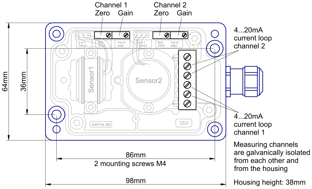
 3D geometry as STEP file
Dimensions (in mm)
Block Diagram
Connections
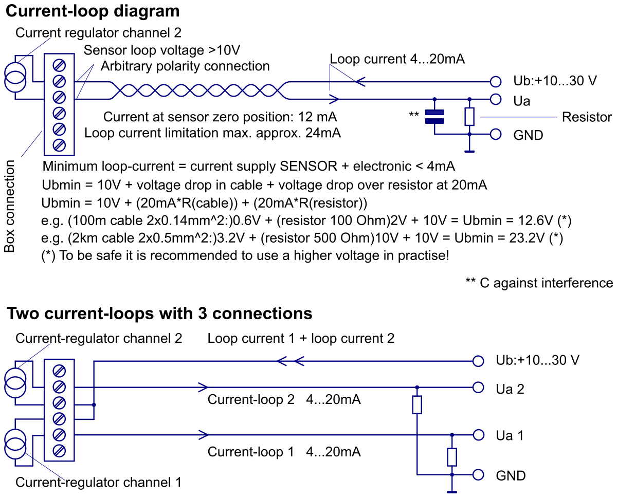
Computing the minimal operating voltage Ub,min
Ub,min = 10V + voltage drop at cabel + load resistor voltage drop at 20mA
Ub,min = 10V + 20mA·Rcabel + 20mA·Rload
Example computations:
Ub,min = 10V + (100m wire 2x0.14mm2) 0.6V + (100 Ohm load) 2V = 12.6V
Ub,min = 10V + (2km cabel 2x0.5mm2) 3.2V + (500 Ohm load) 10V = 23.2V
Basic information
These installation and operating instructions are intended to provide you with the information you need to install and commission the SB2I sensor box correctly and in accordance with regulations in potentially explosive atmospheres. Installation, commissioning and testing may only be carried out by trained and qualified personnel with knowledge of the relevant national regulations on explosion protection. For proper, trouble-free and safe operation of the sensor box, these operating instructions must be read carefully and observed. SEIKA is not liable for damage caused by failure to observe the instructions in this operating manual. Under no circumstances is it permitted to modify the device.
These operating instructions for the SB2I sensor box must be stored in such a way that they can be consulted by authorized persons at any time. No chapters may be removed from this manual at any time. A missing operating manual or missing pages in an operating manual must be replaced immediately. SEIKA can send you new operating instructions on request. The operating instructions must be passed on to any subsequent user of this product.
Legal information
SEIKA Mikrosystemtechnik GmbH gives no implied warranties for standard commercial properties and suitability for a specific purpose. If the device is improperly opened, modified or incorrectly connected to the electrical circuits, the explosion protection warranty and thus the warranty of SEIKA Mikrosystemtechnik GmbH for safe operation in potentially explosive atmospheres is void. SEIKA Mikrosystemtechnik GmbH is in no case liable for personal injury or property damage caused by improper operation of the sensors.
Declaration of conformity
SEIKA SB2I sensor boxes for potentially explosive atmospheres are tested for electromagnetic compatibility and interference emission in accordance with the EMC directives and meet the requirements of the applicable statutory EMC directives. They cannot be operated independently. They must be connected to a power source via a cable and output analog signals for electronic processing. A declaration of conformity is available for all sensors. This is available on request.
As the EMC compatibility of the entire measuring system also depends on the cable routing, the correct connection of the shielding and each device connected to the system, it must be ensured that all components meet the requirements of the EMC Directive and that the electromagnetic compatibility of the entire system or machine is guaranteed.
SEIKA sensor boxes are approved for use in potentially explosive atmospheres and meet the essential health and safety requirements by complying with EN IEC 60079-0:2018, EN IEC 60079-7:2015/A1:2018, EN 60079-11:2012 and EN 60079-31:2014. The mark of EC conformity is the CE mark, which is affixed to all sensor boxes.
All certificates for ATEX certification and electromagnetic compatibility testing can be found at
www.seika.de.
Special instructions for the use of SEIKA SB2I in potentially explosive atmospheres
The intrinsically safe device II 2 G EX ia IIC T4 Gb and II 2 D Ex ia IIIC T135°C Db (Zone 1) may only be connected to certified intrinsically safe circuits. In this version, a cable of at least one meter must be preassembled (other cable lengths optional).
The following maximum values must not be exceeded per channel:
Ui = 30V, Ii = 78mA, Ci = 24nF, Li = 66μH
The II 3 G Ex ec IIC T4 Gc and II 3 D Ex tc IIIC T135°C Dc can be operated without an isolator in zone 2 and zone 22, whereby the power supply unit must not exceed the nominal values.
Nominal values per channel:
Un = 30V, In = 40mA
Installing the sensor box
1. Depending on the measuring plane, the surface should be prepared for the position of the two fixing holes for M4 screws. See image: Dimensions
2. Remove the 4 screws on the top of the box to lift the cover.
3. If the device is supplied with a connected cable, please go to point 6, otherwise go to point 4.
4. Prepare a pair of shielded Ex cables for the circuits and cut them to the required length.
5. Insert the cable through the M16x1.5 cable gland and connect the cable cores to the internal connector strip. See illustration: Connections
6. Screw the device to the mounting surface using two M4 screws: Alternatively, you can use an SBB mounting bracket available from SEIKA for fastening. The best mounting location is near the axis of rotation. Please ensure that the mounting surface is level.
7. Refit the appliance cover with the 4 screws. Ensure that the seal is seated correctly.
8. Apply the power supply 10 to 30 VDC as shown in the image: Connections. Observe the minimum current requirements for the desired load resistor. The power supply does not need to be regulated, but the minimum power to be supplied to the board depends on the selected load resistor, see equations for the correct supply voltage in the image: Connections. The maximum load resistance is 500 Ohm.