Sensorbox for use in particularly harsh operating conditions containing two sensors, one signal conditioner with 4...20mA output, one signal conditioner with 0.5 ... 4.5 Volt output and two safety relays for threshold monitoring
Features
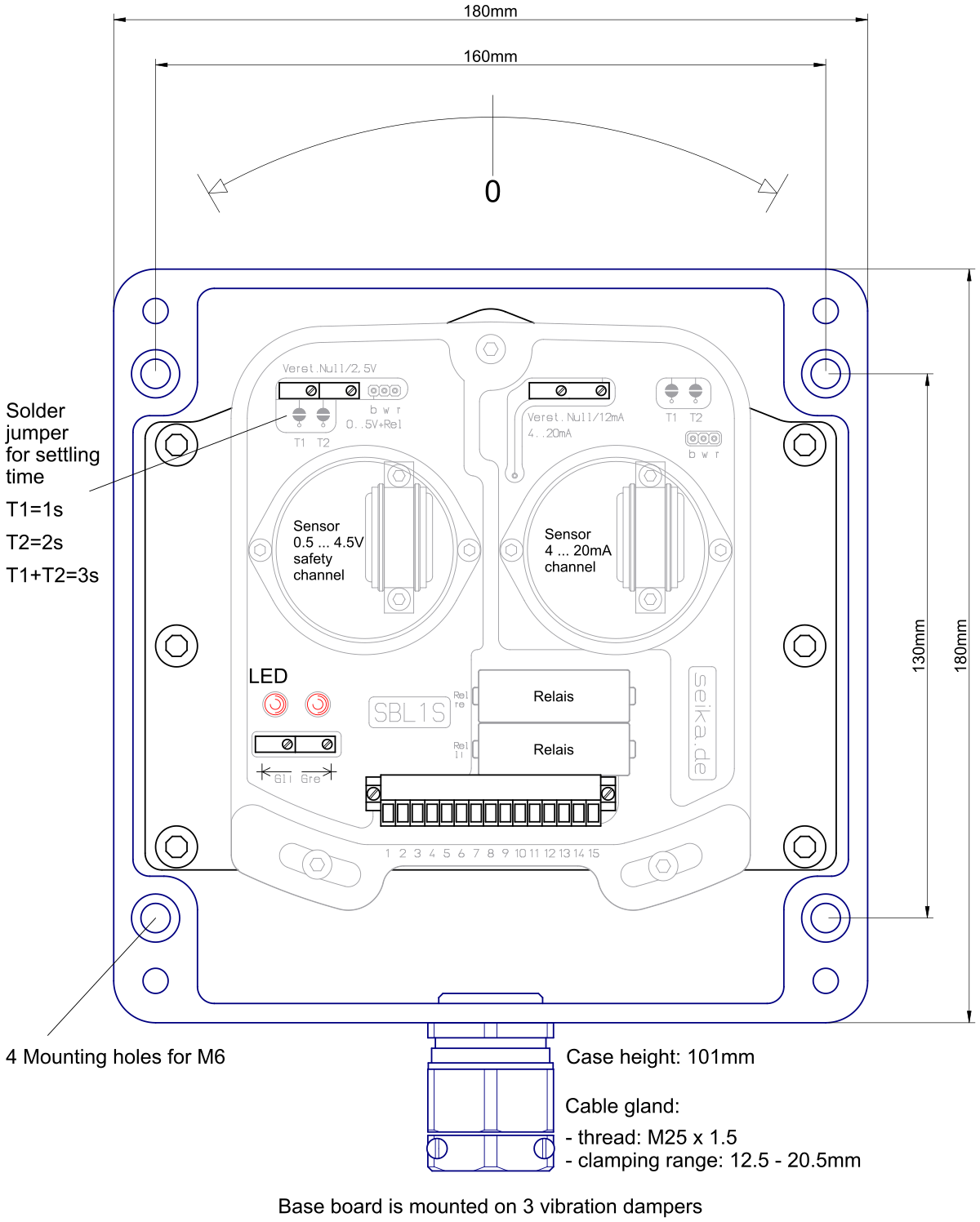
- large, robust pressure die cast aluminium housing (IP67)
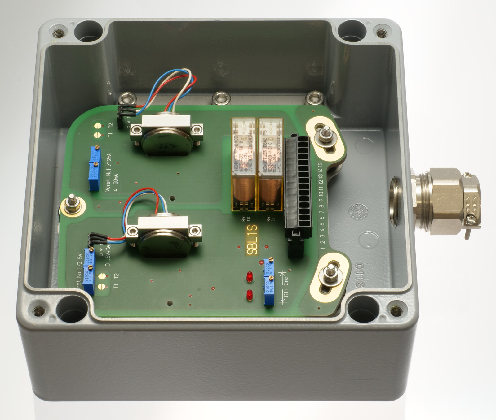
- angular adjustable, vibration damped 3-point fastening of rigid, 3.2mm thick base PCB
- all SEIKA sensors fit the housing and can be installed in different directions of operation
- two integrated, independent measuring channels, electrically isolated from each other and the housing and redundant if operating direction is the same
- Channel 1
- signal conditioner with 4...20mA, 2-wire output
- temperature drift compensation of the sensitivity
- no separate supply voltage necessary
- either connection polarity
- Channel 2
- signal conditioner with 0.5 ... 4.5 Volt output
- temperature drift compensation of the sensitivity
- 12 Volt or 24 Volt supply voltage (standard: 24V)
- either connection polarity
- two separate, individually adjustable safety relay outputs with a separate open and a separate close mechanism each
- Both channels
- the output signals for each sensor are calibrated to customer's specifications
- extensive EMC protection
- highly stable sensor supply voltage
- high mechanical overload resistance
- low pass filter with optional choice of cut-off frequency for suppression of interference frequencies
Description
The SBL1S is a pressure die cast aluminium housing (IP67) with two integrated sensors for uniaxial measurement of inclinations.
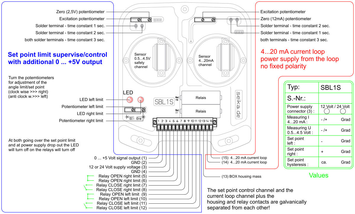
In addition to the sensors, the housing contains one signal conditioner with 4...20mA output and one signal conditioner with 0.5 ... 4.5 Volt output. These include active low pass filters, whose upper cut-off frequencies / settling times can be adjusted to fit the measuring task, and noise voltage filters to ensure the EMC. Interference signals caused by undefined ground currents are eliminated by electrically isolating sensors and signal conditioners from each other and the housing. The voltage output of the SBL1S has two switch outputs, each with a safety relay. Two helical potentiometers allow the setting of two trigger thresholds within the measuring range, at which the corresponding relay triggers. Each relay output has an independent opening and closing contact. The switching hysteresis can be adapted to the measurement task. Electronic temperature compensation largely compensates for the temperature drift of the implemented sensors' sensitivity. Optionally, the temperature drift of both offset and sensitivity can be reduced significantly through individual compensation.
The compact metal cable gland and compact housing size in combination with the 15-wire connection enable the use of this high quality measuring system in harsh operating conditions.
Application
The SBL1S has its application in areas requiring precise inclination measurements under harsh circumstances and consideration of special safety demands. Areas of successful implementation include construction, mining (especially large open pit mining machinery), agricultural machinery, transportation and conveyor systems, ships, operation and automation technology as well as general mechanical engineering.
Specifications
| Terminal connector | 15-channel x 1.5mm2 (pin rail) |
| Cable gland | M25 x 1.5, metal cable gland with integrated strain relief, clamping range 12.5mm ... 20.5mm |
| Measuring range, Resolution, etc. | dependent on implemented SEIKA sensor |
| Degree of protection | IP67 |
| Mounting orientation | any (standard: wall mounting, cable down) |
| Measuring planes (N-, NB-sensor) | 3 main housing planes |
| Measuring plane (NG-sensor) | parallel to housing bottom |
| Operating temperature | -40°C ... +85°C |
| Channel 1 | 4...20mA current output |
| Terminal voltage | 10V ... 30V |
| Minimum loop current | 2.5mA ... 3.5mA |
| Maximum loop current | 23mA ... 26mA |
| Output loop current | 4...20mA (12mA for sensor zero position) |
| Adjustable variables | zero (12mA), amplification |
| Maximum load resistance | 500 Ohm (at 24 Volt supply voltage) |
| Channel 2 | 0.5 ... 4.5 Volt voltage and relay output |
| Supply voltage optional | 12 Volt or 24 Volt (standard: 24V) |
| Operating current | max. 10mA |
| Normalized output range | 0.5V ... 4.5V |
| Zero voltage | 2.5 Volt |
| Maximum output range | 0.05V ... 4.95V |
| Output impedance | 100 Ohm |
| Capacitive output signal loading capacity | any, taking dynamic requirements into account |
| Switching stages | two SIEMENS safety relays SA2A311; these relays comply with safety regulations |
| Contacts | an independent open and close contact per relay |
| Contact loading capacity | 250 Volt, 6 Ampere |
| Adjustable variables | zero (2.5V), amplification, upper and lower trigger threshold |
| Low pass filter | active, 4th order, minimal ripple |
| Weight | approx. 2.5kg |
- • The box is delivered with an individual calibration record that includes the precise offset and sensitivity values, the static characteristic curve and the linearity deviation curve.
Options:
- • custom switching hysteresis • switching state transition: LOW to HIGH or HIGH to LOW
- • special measuring ranges
 3D geometry as STEP file
Dimensions (in mm)
Connections