
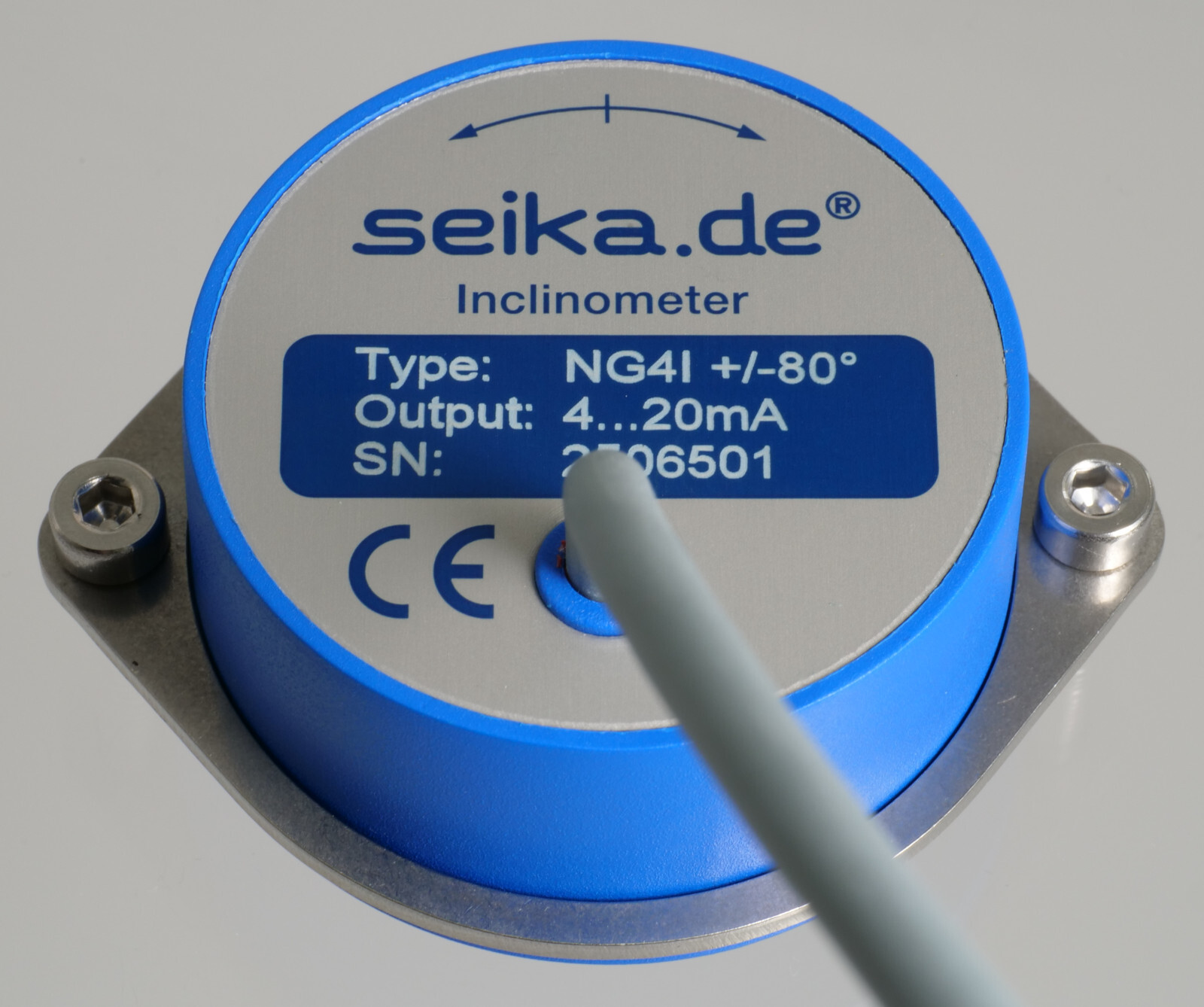
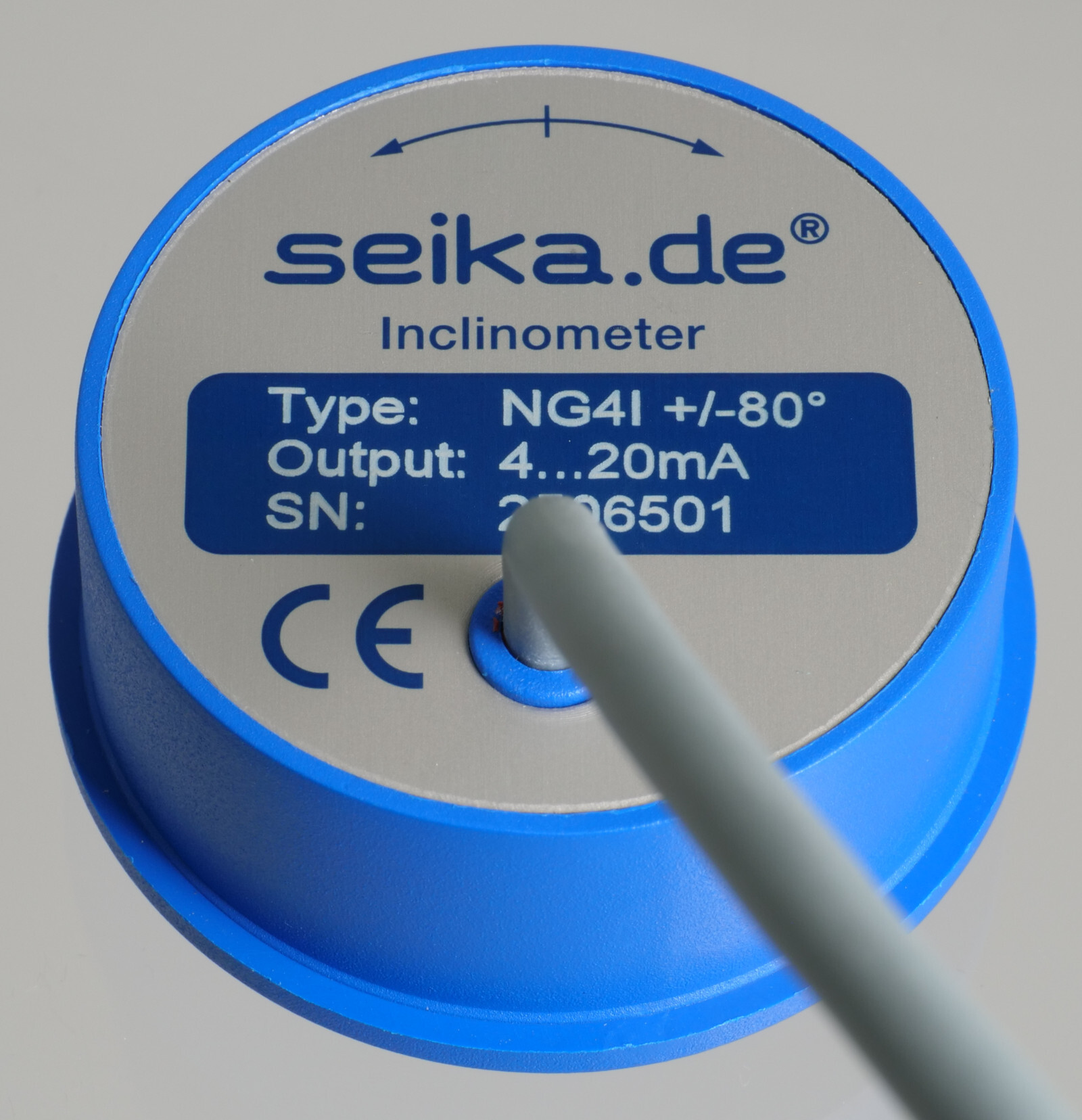
NG2I, NG3I, NG4I
Inclinometers of high measurement accuracy with an integrated 4...20mA signal conditioner for inclination measurement in the ranges of ±10, ±30 and ±80 degrees
Features
- integrated sensor electronics including signal conditioner
- normalized 4...20mA output signal
- electronic compensation of the temperature drift of the sensitivity
- 2-wire connection - sensor power obtained from current loop
- linear output characteristics
- high measurement accuracy
- minimal linearity deviation
- high long-term stability
- hysteresis free output signal
- no interference by ambient electromagnetic fields
- shock proof as without moving mechanical parts
- hermetically sealed
- sensor electrically isolated from point of measurement - no ground connection
- zero point adjustable through 360° using clamping ring
- loop current limitation
- EMC certified
Description
The NG2I, NG3I and NG4I are capacitive and liquid based inclinometers with integrated sensor electronics and current amplifier. Electronic temperature compensation makes up for the temperature drift of the sensitivity of the primary transformer. An integrated, highly stable voltage regulator ensures stable operation for a range of supply voltages. The measurement technique provides a linear relationship between the angle to be measured (up to 80 degrees for the NG4I) and the output signal that is calibrated during manufacture. The measuring time constant can be matched to the requirements of the measurement task by appropriate hardware programming. The power is obtained from the measurement current loop, thereby eliminating the need for a separate power supply and enabling operation with two wire connection.
Application
The NG2I, NG3I and NG4I are suitable for applications requiring high measurement accuracy with high linearity and temperature stability as well as high long-term stability for measurement of large inclination angles and for which the power is to be supplied via a 4...20mA current loop without the need for a separate supply voltage. We recommend the sensorbox SB1I with an integrated NG - inclinometer and a 4...20mA output signal for operation in especially harsh operating conditions. These inclinometers are typically used in construction, mining, vehicles, aircraft, ships, transportation and conveyor systems and process control as well as for safety engineering.
Specifications
| Type | NG2I | NG3I | NG4I |
|---|---|---|---|
| Measuring range | ±10 degrees | ±30 degrees | ±80 degrees |
| Resolution | <0.001 degrees | <0.003 degrees | <0.01 degrees |
| Standardized sensitivity (other normalization on request) | 0.8mA/degree | 0.266mA/degree | 0.1mA/degree |
| Type | NG2I |
|---|---|
| Measuring range | ±10 degrees |
| Resolution | <0.001 degrees |
| Standardized sensitivity (other normalization on request) | 0.8mA/degree |
| Type | NG3I |
|---|---|
| Measuring range | ±30 degrees |
| Resolution | <0.003 degrees |
| Standardized sensitivity (other normalization on request) | 0.266mA/degree |
| Type | NG4I |
|---|---|
| Measuring range | ±80 degrees |
| Resolution | <0.01 degrees |
| Standardized sensitivity (other normalization on request) | 0.1mA/degree |
| Shared specifications | |
|---|---|
| Dimensions | see dimension drawing |
| Linearity deviation | <0.1% of measuring range |
| Transverse sensitivity | <1% at 45° tilt |
| Settling time | approx. 0.3 seconds (1s, 2s or 3s optional) |
| Temperature drift of sensitivity | approx. -0.005(8)%/K |
| Temperature drift of zero point | approx. 0.001(5)°/K |
| Terminal voltage | 10V ... 30V either polarity |
| Output current offset for sensor zero position | 12mA |
| Degree of protection | IP65 |
| Operating temperature | -40°C ... +85°C |
| Storage temperature | -45°C ... +90°C |
| Weight (without clamping ring or cable) | approx. 118g |
| Electrical connection | • 0.5m cable Ø4.6 mm, 2-wires • special lengths on request |
- • Each sensor is calibrated after production. It is delivered with an individual calibration record that includes the precise offset and sensitivity values, the static characteristic curve and the linearity deviation curve.
Options:
- • special measuring range
- • enhanced EMC requirements
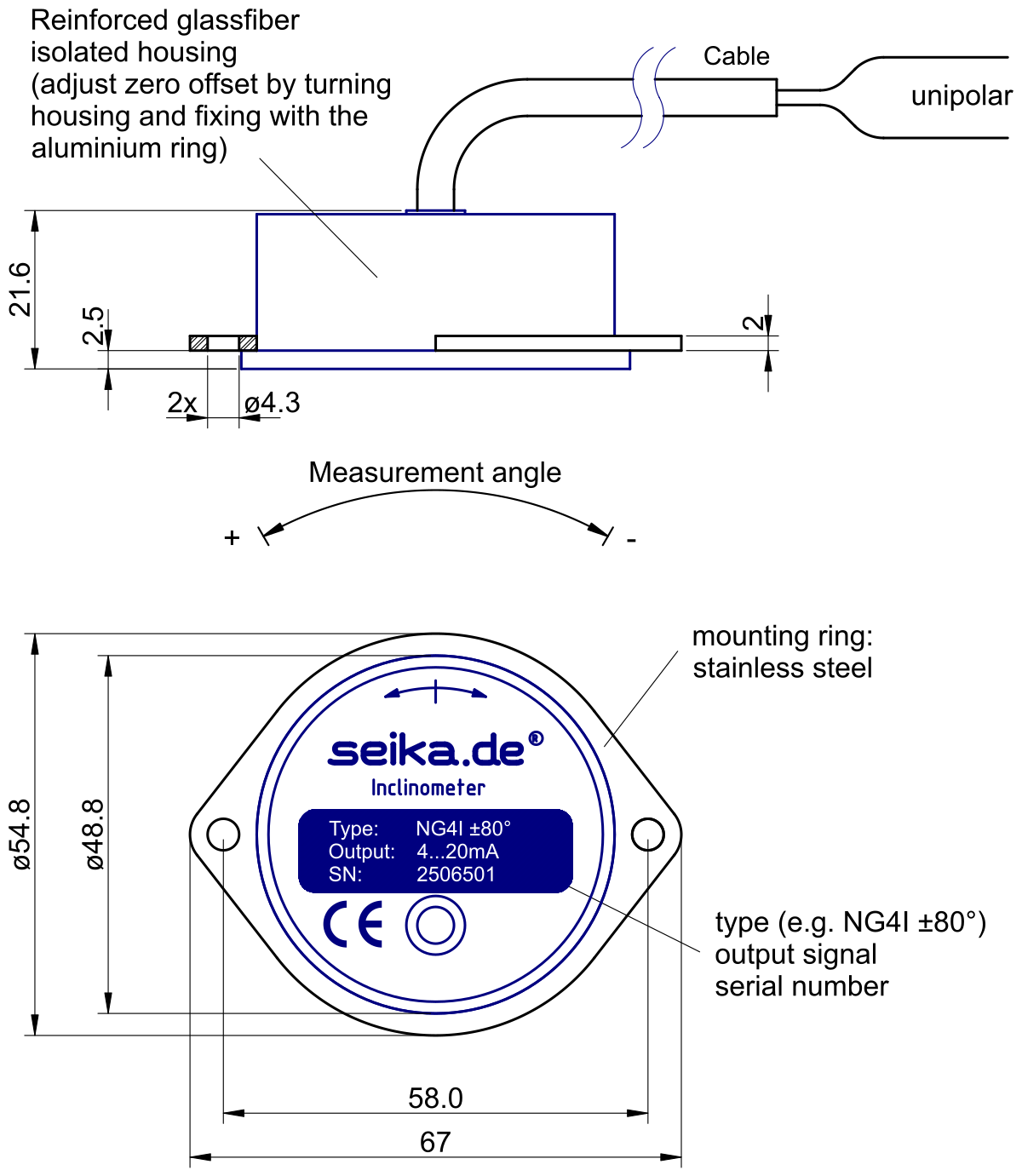
Dimensions (in mm)
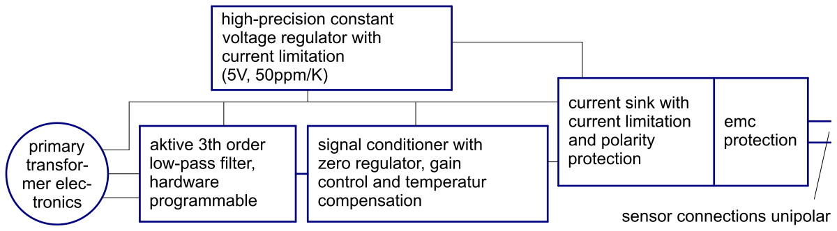
Block diagram
Connections

Computing the minimal operating voltage Ub,min
Ub,min = 10V + voltage drop at cabel + load resistor voltage drop at 20mA
Ub,min = 10V + 20mA·Rcabel + 20mA·Rload
Example computations:
Ub,min = 10V + (100m wire 2x0.14mm2) 0.6V + (100 Ohm load) 2V = 12.6V
Ub,min = 10V + (2km cabel 2x0.5mm2) 3.2V + (500 Ohm load) 10V = 23.2V