
Sensorbox containing one sensor and one signal conditioner with 4...20mA, 2-wire output
Features
- large, robust pressure die cast aluminium housing (IP67)
- angular adjustable, vibration damped 3-point fastening of rigid, 3.2mm thick base PCB
- integrated signal conditioner with 4...20mA, 2-wire output
- temperature drift compensation of the sensitivity
- no separate supply voltage necessary
- all SEIKA sensors fit the housing and can be installed in different directions of operation
- the output signal of the sensor is calibrated to customer's specifications in the required direction of operation
- sensor and signal conditioner electrically isolated from housing
- extensive EMC protection
- highly stable sensor supply voltage
- 10V ... 30V terminal voltage
- loop current limitation
- high mechanical overload resistance
- either connection polarity
- low pass filter with optional choice of cut-off frequency for suppression of interference frequencies
Description
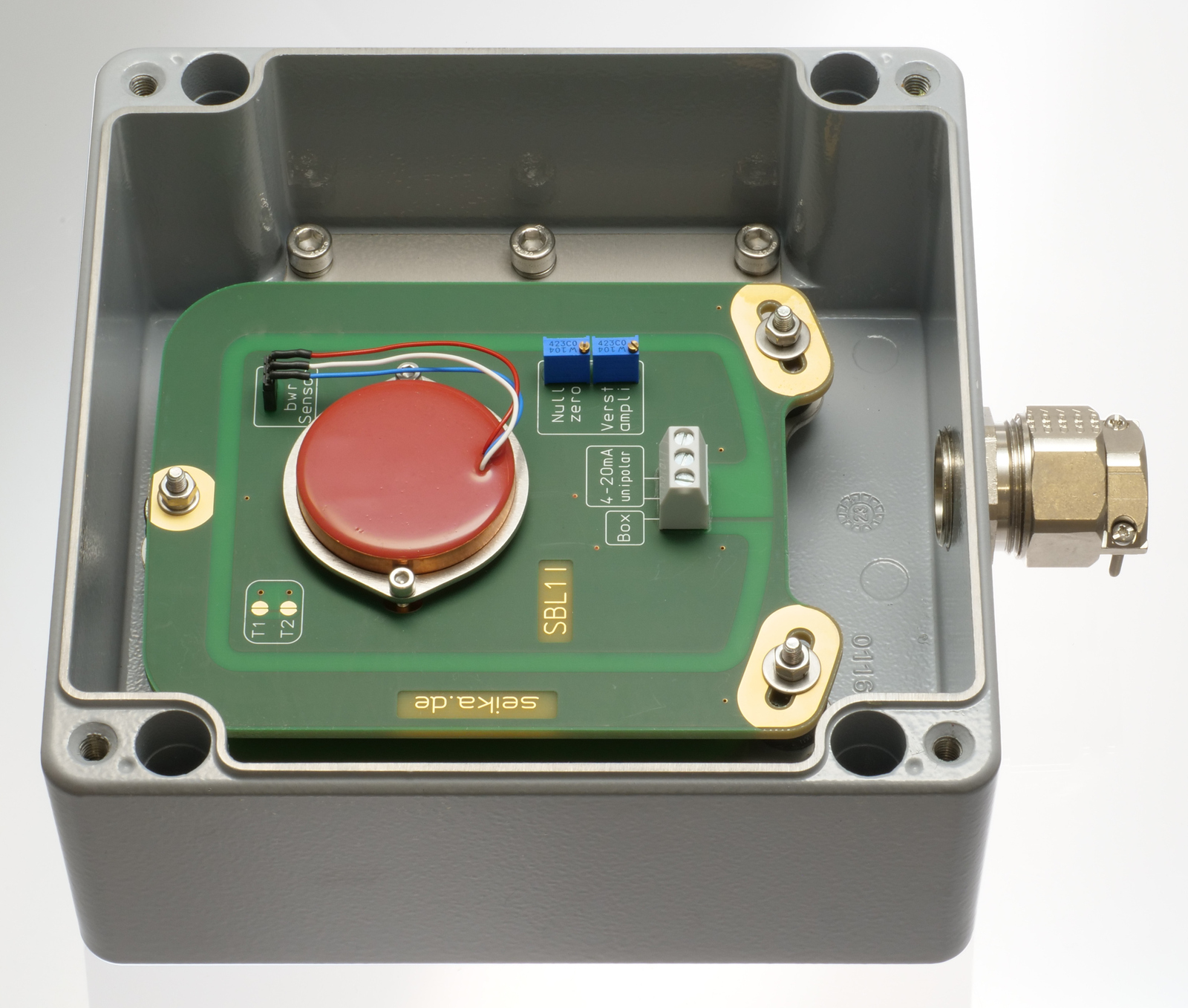
The SBL1I is a large, pressure die cast aluminium housing (IP67) with an integrated sensor for uniaxial inclination measurements.
In addition to the sensor, the box contains a signal conditioner with a 4...20mA, 2-wire output and a separate, highly stable supply voltage for the actual sensor feeding off the current loop. Furthermore, the signal conditioner includes an active low pass filter, whose upper cut-off frequency / settling time can be adjusted to suit the measurement task, an output stage with current limitation, noise voltage filters and a diode bridge for unipolar connection to the current loop. Interference signals caused by unwanted ground currents are eliminated by electrically isolating sensor and signal conditioner from the housing. Electronic temperature compensation largely compensates for the temperature drift of the implemented sensor's sensitivity. Optionally, the temperature drift of both offset and sensitivity can be reduced significantly through individual compensation.
The tight metal cable gland and compact housing size in combination with the 2-wire connection enable the use of this high quality measuring system in harsh operating conditions.
Application
The SBL1I is suited for taking precise inclination or acceleration measurements under harsh circumstances and returning a 4...20mA output signal. Areas of successful implementation include construction, mining (especially large open pit mining machinery), agricultural machinery, transportation and conveyor systems, ships, operation and automation technology as well as general mechanical engineering.
Specifications
| Terminals | 3 x 1.5mm2 (2 signal, 1 GND) |
| Cable fixing | M25 x 1.5, metal cable gland with integrated strain relief, clamping range 12.5mm ... 20.5mm |
| Measuring range, Resolution, etc. | dependent on implemented SEIKA sensor |
| Degree of protection | IP67 |
| Mounting orientation | any (standard: wall mounting, cable down) |
| Measuring planes (N.., NB.. sensor) | 3 main housing planes |
| Measuring plane (NG.. sensor) | parallel to housing bottom |
| Terminal voltage | 10V ... 30V |
| Minimum loop current | 2.1mA ... 3.5mA |
| Maximum loop current | 22mA ... 26mA |
| Output loop current | 4...20mA (12mA in sensor zero position) |
| Adjustable variables | zero (12mA), amplification |
| Maximum load resistance | 500 Ohm (for 24 Volt supply voltage) |
| Operating temperature | -40°C ... +85°C |
| Weight | approx. 2.36kg |
- • The box is delivered with an individual calibration record that includes the precise offset and sensitivity values, the static characteristic curve and the linearity deviation curve.
Options:
- • special measuring ranges • silicon encapsulation • custom wiring
- • individual temperature drift compensation of the offset and the sensitivity
 3D geometry as STEP file
Dimensions (in mm)
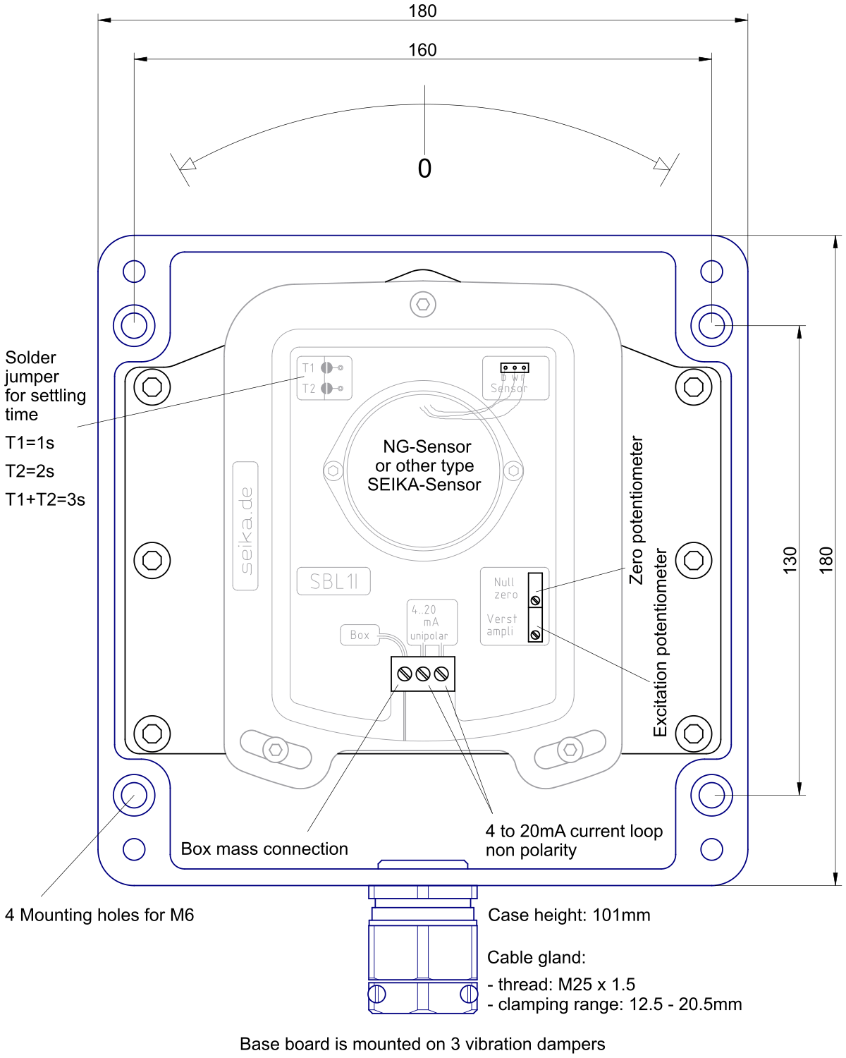
Connections

Computing the minimal operating voltage Ub,min
Ub,min = 10V + voltage drop at cabel + load resistor voltage drop at 20mA
Ub,min = 10V + 20mA·Rcabel + 20mA·Rload
Example computations:
Ub,min = 10V + (100m wire 2x0.14mm2) 0.6V + (100 Ohm load) 2V = 12.6V
Ub,min = 10V + (2km cabel 2x0.5mm2) 3.2V + (500 Ohm load) 10V = 23.2V