
Sensorbox containing one sensor and one signal condtioner with 4...20mA, 2-wire output
Features
- robust pressure die cast aluminium housing (IP67) with saltwater proof coating
- twist free 4-point fastening of rigid, 3.2mm thick base PCB
- integrated signal conditioner with 4...20mA, 2-wire output
- temperature drift compensation of the sensitivity
- no separate supply voltage necessary
- all SEIKA sensors can be installed, in different directions of operation
- the output signal of the sensor is calibrated to customer's specifications in the required direction of operation
- sensor and signal conditioner electrically isolated from housing
- EMC certified
- highly stable sensor supply voltage
- 10V ... 30V terminal voltage
- programmable dynamic response
- loop current limitation
- high mechanical overload resistance
- either connection polarity
- low pass filter with optional choice of cut-off frequency for suppression of interference frequencies
Description
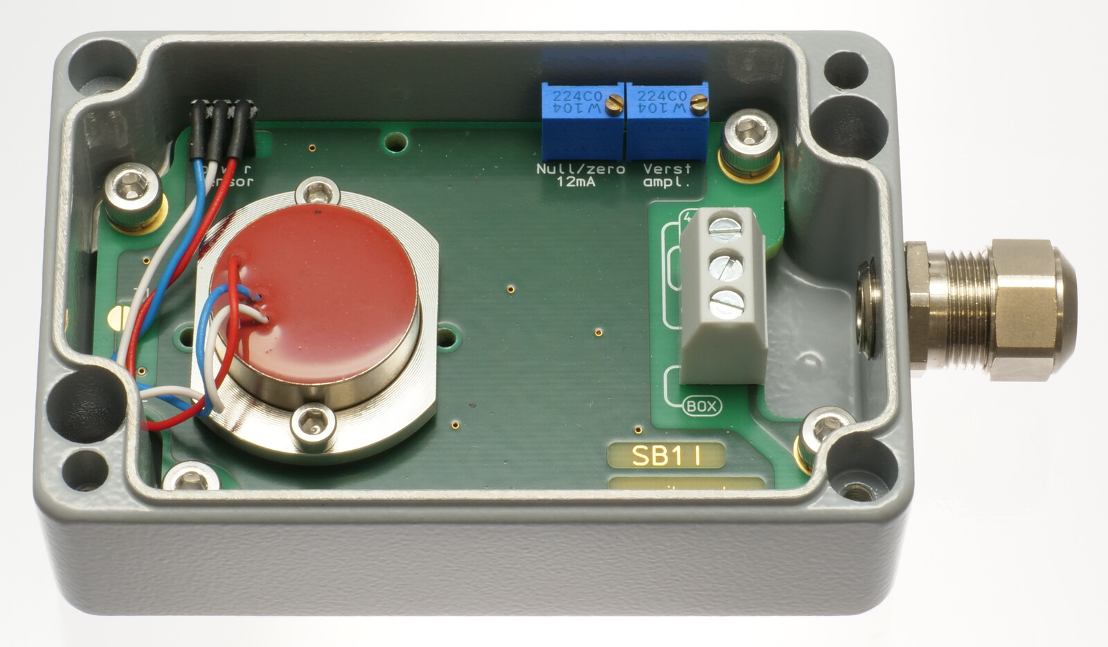
The SB1I is a pressure die cast aluminium sensor housing (IP67) with an integrated sensor for measuring uniaxial acceleration or inclination.
In addition to the sensor, the box contains a signal conditioner with 4...20mA, 2-wire output and a separate, highly stable supply voltage feeding off the current loop. Furthermore, the signal conditioner includes an active low pass filter, whose upper cut-off frequency / settling time can be adjusted to suit the measurement task, an output stage with current limitation, a noise voltage filter and a diode bridge for unipolar coupling to the current loop. Interference signals caused by unwanted ground currents are avoided by electrically isolating sensor and signal conditioner from the housing. Unlike the SB2.., the SB1I can accommodate larger inclinometers, such as the NG-series, that have a higher measuring accuracy. Electronic temperature compensation largely compensates for the temperature drift of the implemented sensor's sensitivity. Optionally, the temperature drift of both offset and sensitivity can be reduced significantly through individual compensation.
The compact metal cable guide and small housing size in combination with the 2-wire connection enable the use of this high quality measuring system in harsh operating conditions.
Application
The SB1I is suitable for applications requiring precise inclination or acceleration measurements under harsh circumstances and returning of a 4...20mA output signal. Areas of successful implementation include construction, mining, agricultural machinery, transportation and conveyor systems, ships, operation and automation technology as well as general mechanical engineering.
Specifications
| Terminals | 3 x 1.5 mm2 |
| Cable gland | M12 x 1.5, metal cable gland with integrated strain relief, clamping range 6mm ... 7.5mm |
| Measuring range, Resolution, etc. | depending on implemented SEIKA sensor |
| Degree of protection | IP67 |
| Mounting orientation | any (standard: wall mounting, cable on the right) |
| Measuring planes (N sensor) | 3 main housing planes |
| Measuring plane (NG sensor) | parallel to bottom of housing |
| Measuring directions (B or BDK sensor) | X,Y,Z coordinates of housing |
| Torque housing lid | 1.5Nm |
| Terminal voltage | 10V ... 30V |
| Minimum loop current | 2.1mA ... 3.5mA |
| Maximum loop current | 22mA ... 26mA |
| Output signal loop current | 4...20mA (12mA for sensor zero position) |
| Adjustable variables | zero point (12mA), amplification |
| Maximum load resistance | 500 Ohm (for 24 Volt supply voltage) |
| Operating temperature | -40°C ... +85°C |
| Weight | approx. 300g |
- • The box is delivered with an individual calibration record that includes the precise offset and sensitivity values, the static characteristic curve and the linearity deviation curve.
Options:
- • special measuring ranges • silicon encapsulation • custom wiring
- • individual temperature drift compensation of the offset and the sensitivity
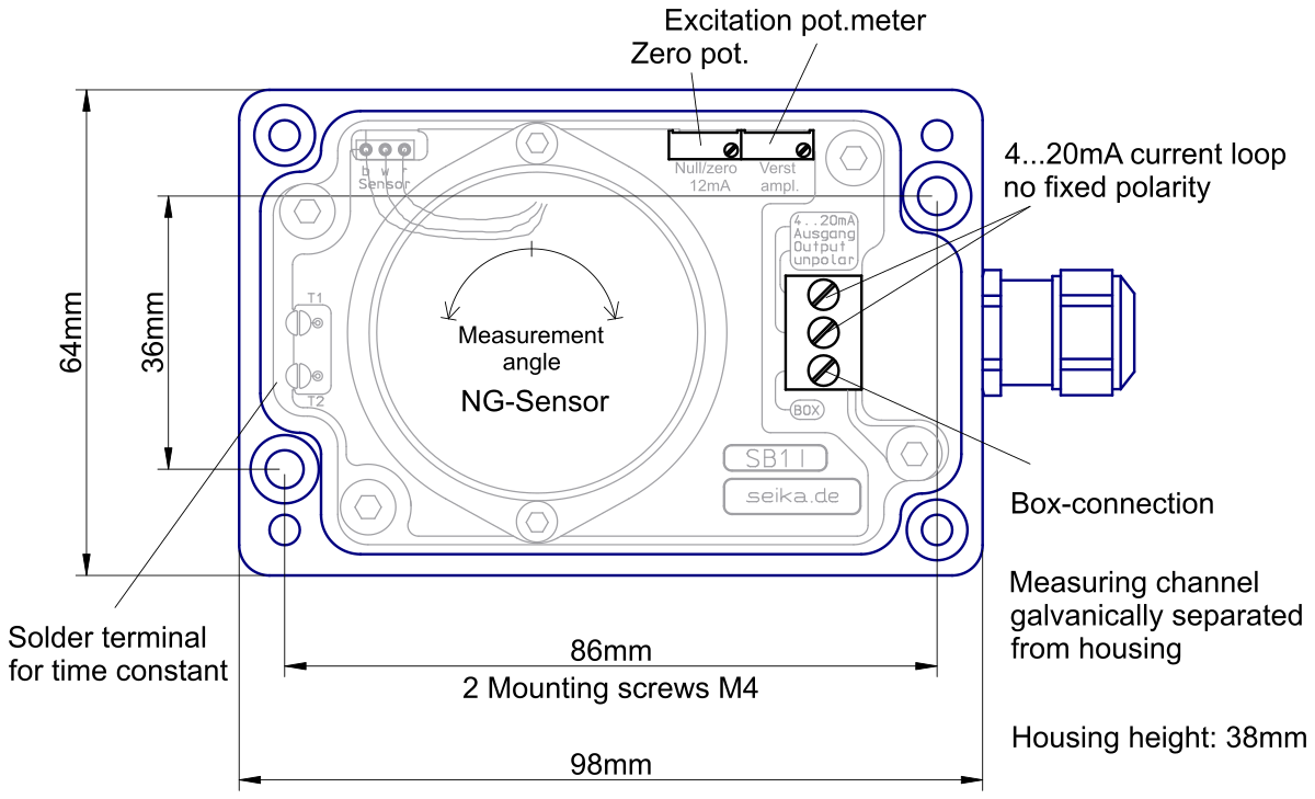
 3D geometry as STEP file
Dimensions (in mm) of SB1I containing NG inclinometer
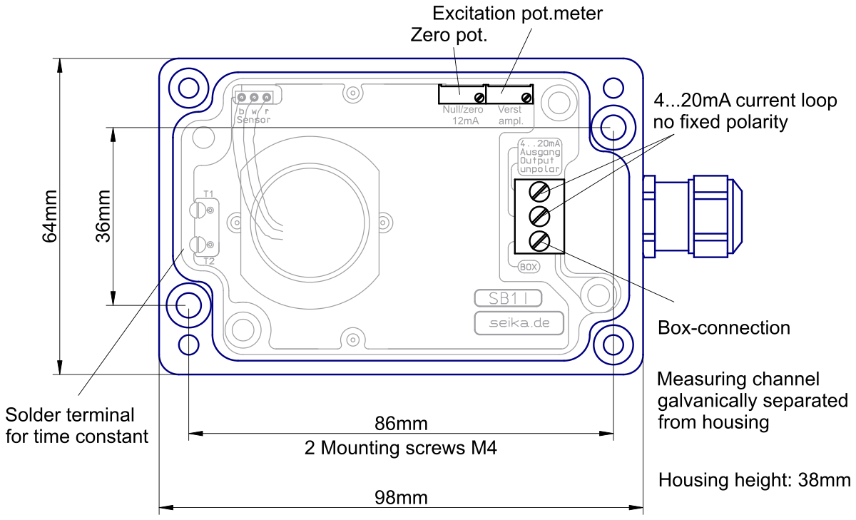
Dimensions (in mm) and Measuring Directions of SB1I with N inclinometer


Connections

Since the SB1I supply voltage feeds off the current loop (the SB1I requires 3mA at most), a voltage of 10V across the SB1I terminals must be guaranteed to ensure correct functionality even for the maximum loop current of 24mA (maximum voltage drop across transmission line and load resistance).
Computing the minimal operating voltage Ub,min
Ub,min = 10V + voltage drop at cabel + load resistor voltage drop at 20mA
Ub,min = 10V + 20mA·Rcabel + 20mA·Rload
Example computations:
Ub,min = 10V + (100m wire 2x0.14mm2) 0.6V + (100 Ohm load) 2V = 12.6V
Ub,min = 10V + (2km cabel 2x0.5mm2) 3.2V + (500 Ohm load) 10V = 23.2V